May 26, 2018 / by David Wehr / In How-To / 4 commetns
Serial communication via audio on Android
In this blog post, we’ll go over how to send serial data from an Android phone using just the audio port.
When working on AndroWobble, we needed a low-latency way to send data from an Android phone to an Arduino microcontroller. Revisiting this over a year later, I’m not sure why we didn’t simply buy a USB On-The-Go (OTG) cable and communicate that way, so I’ll pretend that we had a good reason for doing this. Regardless, many microcontrollers don’t have a USB to TTL chip like the Arduino has, so being able to send raw serial data from a phone is still useful.
All Nearly all phones have a headphone jack, which can create arbitrary waveforms, and what is a digital signal but a specific waveform?
So, let’s see if can send a serial signal out the audio port.
Serial Communication
Here’s a refresher on the asynchronous serial protocol. It runs at a pre-specified baud rate (commonly 9600, 57600, or 115200), which determines how wide each pulse is. Data is sent in “frames”, which include
- A start bit (low logic level)
- 5-9 data bits
- An optional parity bit
- 1-2 stop bits (high logic level)
It’s asynchronous, so when nothing is being sent, the line is held high until the next data frame. Sparkfun has a good article with more details, if you’re not familiar.
To send the waveform, we make use of the phone’s digital to analog converter (DAC). These can be guaranteed to process at least 44 100 samples per second (44.1 kHz), which ensures that they can recreate the entire audible frequency range (See the Nyquist rate). In practice, they typically run at 48 kHz.
Audio output
To create the correct waveform, we can use the Android NDK and the Oboe library for high-performance audio.
With 8-bit data chunks, there are only 256 unique frames that we might send, so they can be pre-generated and stored in a table.
Below is code for creating the wave table.
With the comments, it should be clear enough; for each audio sample, we figure out which bit of the frame is being output, and set the audio to ± MAXIMUM_AMPLITUDE_VALUE.
For 16-bit PCM, this is ± 32 768.
1
2
3
4
5
6
7
8
9
10
11
12
13
14
15
16
17
18
19
20
21
22
23
24
25
26
27
28
29
30
31
32
33
// Number of bits in each byte frame (start bits, stop bits, data)
int byte_frame_bits = DATA_BITS + START_BITS + STOP_BITS;
// Number of samples per UART bit
float bit_width = sample_rate / BAUD_RATE;
// Number of samples per byte frame
frame_width = std::ceil(byte_frame_bits * bit_width);

// Fill out bytes wavetable
for (int byte = 0; byte < bytes_wavetable.size(); byte++) {
    auto& wave = bytes_wavetable[byte];
    wave.resize(frame_width);

    for (int i = 0; i < frame_width; i++) {
        int bit_id = std::floor((float) i / bit_width - START_BITS);
        int16_t to_send;
        // start bits
        if (bit_id < 0) {
            to_send = -MAXIMUM_AMPLITUDE_VALUE;
        }
        // data bits
        else if (bit_id < DATA_BITS && bit_id >= 0) {
            // 0/1 bit to send
            uint8_t bit_send = (byte >> bit_id) & (0x01);
            // 0/1 expanded to minimum or maximum amplitude
            to_send = ((2 * bit_send) - 1) * MAXIMUM_AMPLITUDE_VALUE;
        }
        // stop bit and holding line high to indicate no data
        else {
            to_send = MAXIMUM_AMPLITUDE_VALUE;
        }
        wave[i] = to_send;
    }
}
Oboe allows you to set a callback whenever new audio data is needed (AudioStreamCallback::onAudioReady()), so we can copy the frames from the table into the output audio buffer, or if there is no data to send, fill the buffer with line high values.
Shaping the signal
Great, so we can just send our waveform out through the audio port at 24 kilobaud (two samples are needed to make a square wave)! Not so fast.
There are two problems to handle:
- Firstly, the output is in the range of ± 1.5V; we need 0V-5V.
- Secondly, an audio DAC doesn’t actually output the samples directly as given. It’s trying to recreate a sampled audio signal, so it will do fancy interpolation. (Read about the Nyquist-Shannon sampling theorem and the sinc function to learn more.)
Below is an oscilloscope probe showing what the raw signal out of the DAC looks like (green), and what we’d like it to look like (orange). Note that the two signals have different vertical scaling and offset.
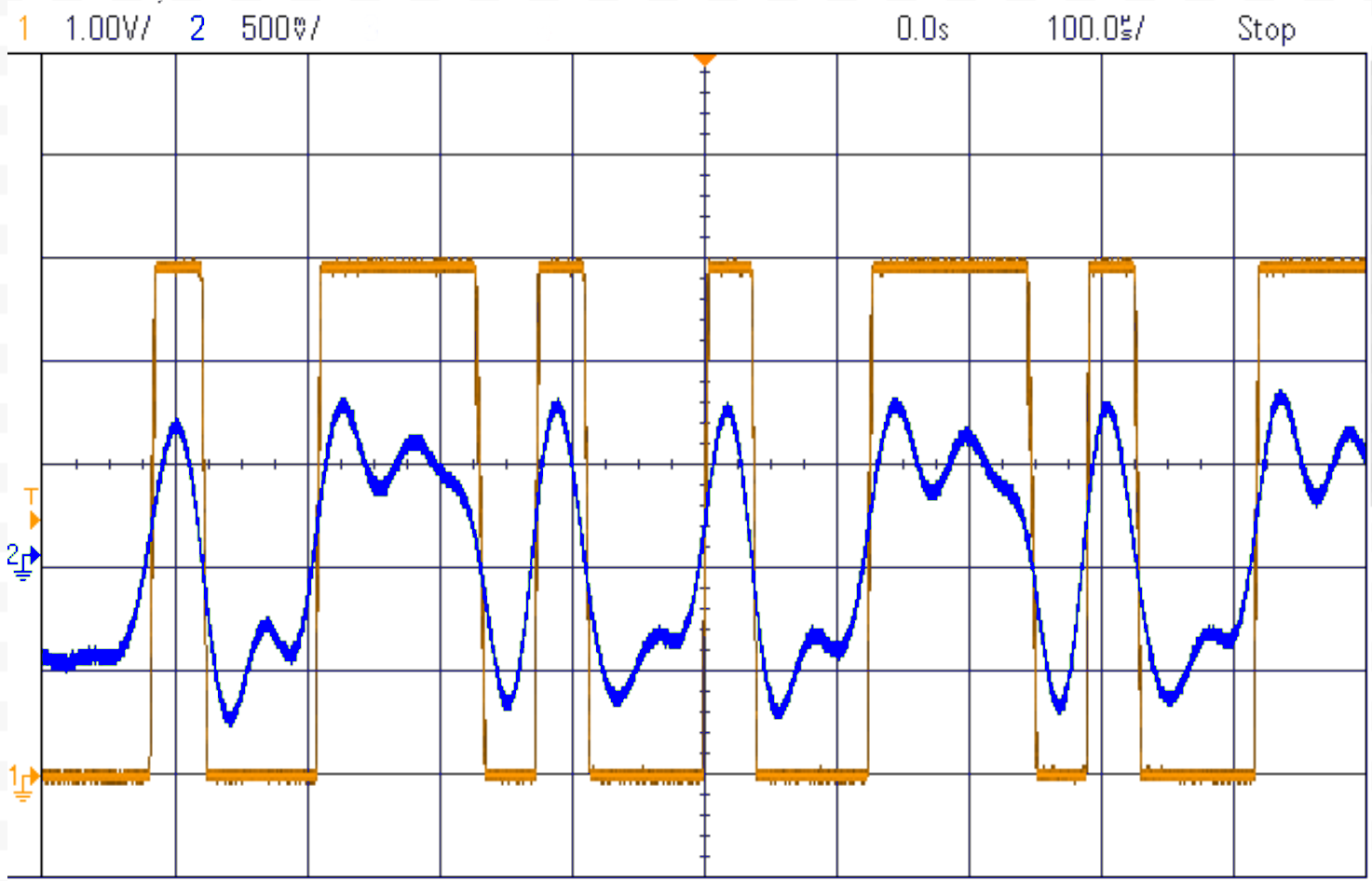
With an op-amp, we can design a comparator circuit that will output 0V when the signal is negative, and +5V when the signal is positive. Here is a good article on ElectronicsTutorials with more info about op-amp comparators.
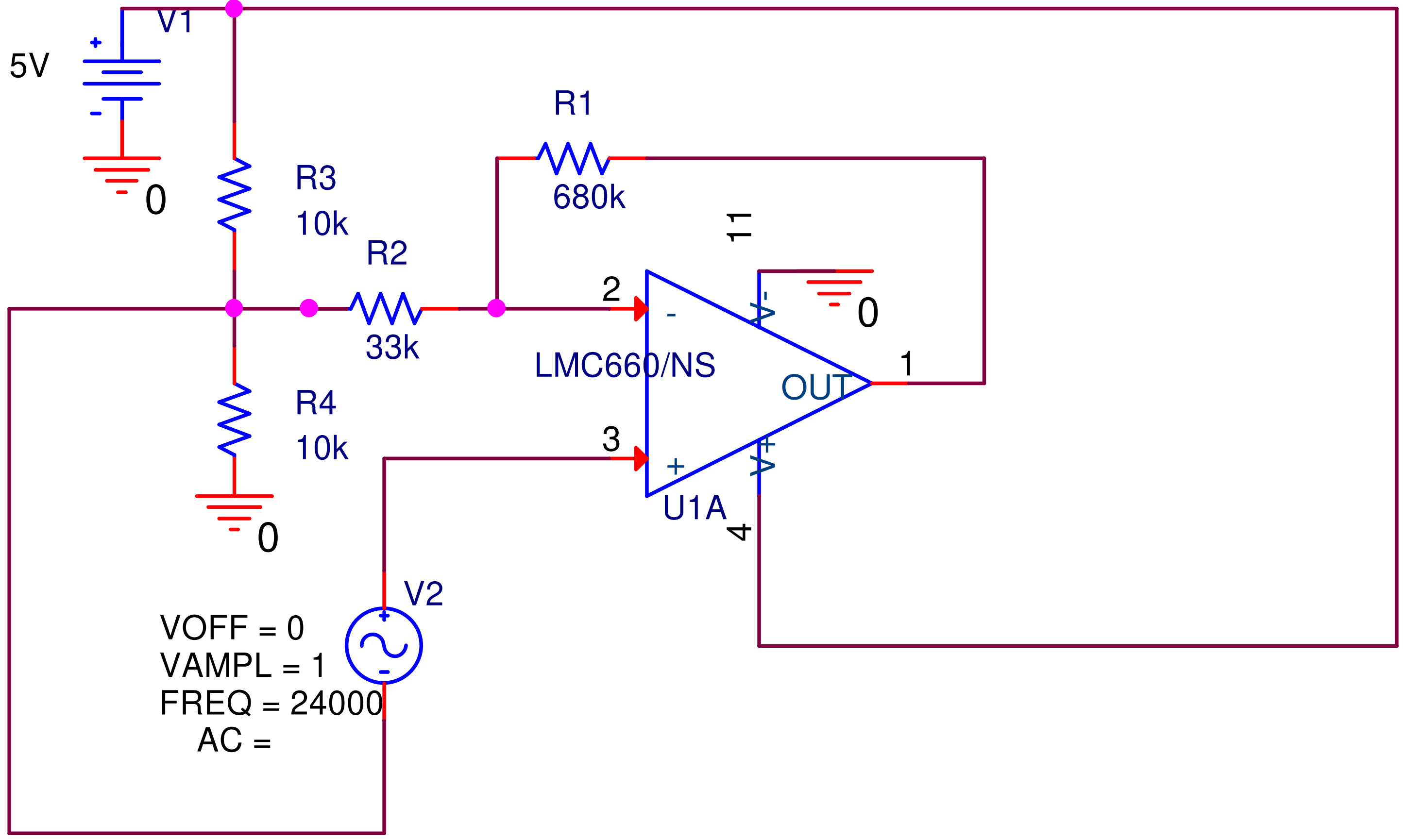
The input audio signal is represented by V2, and the output appears at the op-amp OUT terminal. The circuit is a non-inverting comparator with positive feedback (resulting in hysteresis for stability near the zero crossover point). Resistors R3 and R4 form a voltage divider to make the reference voltage of 2.5V. Then the incoming audio signal is biased by +2.5V by connecting audio ground to the reference 2.5V. Therefore, comparing the biased input to 2.5V is equivalent to comparing to 0V. The output goes from 0V-5V because the op-amp is powered by a 5V supply, and its output is rail-to-rail.
Don’t forget to connect the power supply ground to the ground of whatever is reading the serial signal. You wouldn’t believe how many times I’ve forgetten to do that!
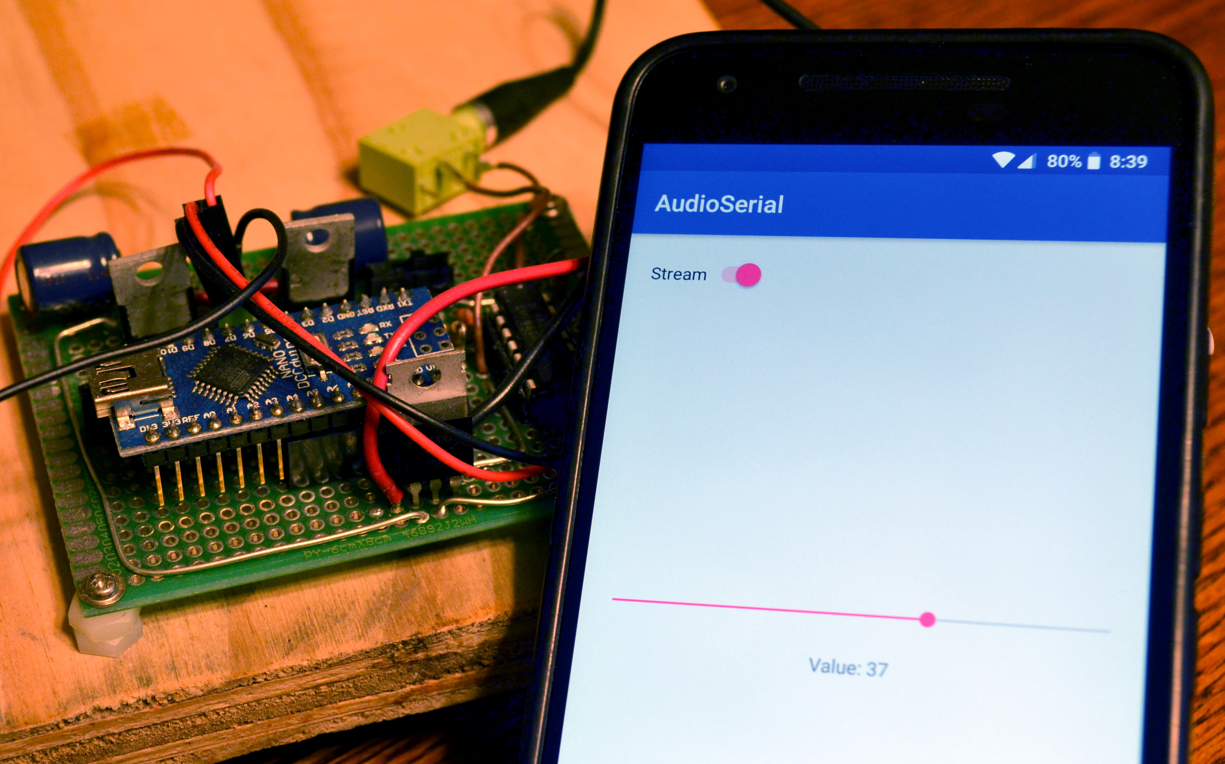
Example
We used this technique when making AndroWobble, but it used the now deprecated Howie library. So I made a simple app using Oboe to demonstrate a complete example. The full code is on GitHub, and a video of controlling a motor by sending data to an Arduino is below.